
Pipeline Manual
Master fluids, pressure, head lift and advanced pipe networks.
Belts are forgiving. Pipes are not. A pipe network that looked perfect on paper can starve half a refinery row, stall a bank of fuel generators or simply refuse to climb a cliff — and the game tells you almost nothing about why. This guide walks through the whole model: how a pipe decides how fast it flows, what head lift really measures, and which arrangements of pumps, buffers, valves and junctions solve the problems that come up in practice.
This page is an interactive adaptation of The FICSIT Inc. Plumbing Manual: A Guide to Pipelines. Every rule, number and example comes from that manual; the diagrams, calculators and knowledge checks are ours.
- Manual version
- 1.4
- Date
- 21.08.2022
- Written for
- Update 5 + Update 6 (+ onward)
The manual predates the current release. We kept it faithful to its source rather than re-testing every statement against the latest patch, so treat the numbers as the manual’s findings, not as independently verified data.
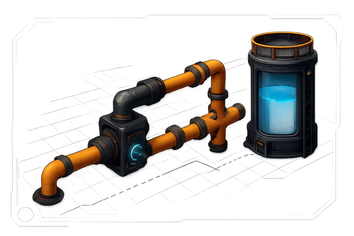
General pipe behaviour
Pipelines are heavily simplified compared to real plumbing. Three properties explain almost everything they do.
A pipe has no preferred direction. Fluid can flow either way through it.
A pipe will always flow downwards first, if it can.
Pipes use pressure to move fluid. That movement is the .
Those three lead to the behaviour you actually see in the field:
- Pipes build up pressure as they fill. The fuller they are, the faster they flow — a pipe on its own contributes about
1.2 mof head lift. - Fluid flows from high pressure to low pressure, which in practice means from a full pipe towards a less full one.
- Until a pipe’s internal volume is full, it cannot transmit from a machine or a pump.
How much fluid is moving through the pipe right now, per minute.
The pipe’s ceiling. It can never flow faster than this.
The internal volume — the bubble icon. It shows how full the pipe is, and it is the number that decides everything else.
A pipe can only flow at maximum speed if it is full. At 50 % full it flows half as fast. The manual’s own example: a Mk.1 pipe holding 6 of 10 m³ flows at 180 m³/min, not 300.
Pipe fill and flow rate
InteractiveReproduces the manual's example: a Mk.1 pipe holding 6 of 10 m³ flows at 180 m³/min.
| Pipeline | Maximum flow rate |
|---|---|
| Pipeline Mk.1 | 300 m³/min |
| Pipeline Mk.2 | 600 m³/min |
Rule Full Pipes are happy Pipes
Knowledge check
OptionalA pipe runs up a rock face in three sections. In which order do A, B and C fill up?
Pick the options in order
The same rule explains a display that confuses almost everyone. A Water Extractor at 100 % clock speed produces 120 m³/min — but its gauge reads 300 m³/min, and it says its maximum is 600.
- Max Flow Rate is the speed at which pipes can flow and machines can empty themselves.
- Flow Rate is the speed at which the machine is outputting fluid at this instant.
- Pipes try to flow at maximum speed when they are full — and machines do this all the time. Every time a machine produces fluid, it tries to empty itself as fast as the connected pipe allows.
- So the extractor empties at
300 m³/min(the Mk.1 pipe’s limit) until it is empty, then waits. On average it still puts out its120 m³/min. The600is what it could do with a Mk.2 pipe and no valve in the way.
Pressure and head lift
Pipes have two kinds of pressure. Only one of them is worth your attention.
The two are and . We will only talk about head lift here, because work pressure is neither easily manipulated nor easily noticed.
- Head lift determines the maximum height fluid can flow to. Everything else about it follows from that one sentence.
- It is transmitted through full pipes and does not decline along them. A
50 mpump still has50 mat the far end of a full pipe. - The exception is an unpowered pump: it sets the head lift on its exit side to
0 m. do not block head lift. - Head lift is only about verticality. Horizontal pipes do not need it to keep their flow rate up.
| Source | Head lift | With the ~12 % tolerance |
|---|---|---|
| Normal machines (Water Extractor, Fluid Freight Platform, …) | 10 m | ≈ 12 m |
| Pipeline Pump Mk.1 | 20 m | ≈ 22 m |
| Pipeline Pump Mk.2 | 50 m | ≈ 55 m |
| Fluid Buffer (400 m³) | up to 8 m | depends on fill level |
| Industrial Fluid Buffer (2400 m³) | up to 12 m | depends on fill level |
Head lift calculator
InteractiveValues from lesson 2 of the manual, including the ~12 % tolerance it measured.
Flow management
How much pipe do you actually need? Less than you think — as long as you count the right thing.
Take six machines that each need 100 m³/min, on Mk.1 pipe. Feed the row with 300 m³/min from the left and 300 m³/min from the right and it works: the left 300 is exactly enough for the first three taps, the right 300 for the other three. In fact the pipe in the middle is not even needed — the two halves never exchange fluid.
Now make each output 150 m³/min and feed the row from two points inside it. It looks like a bottleneck, and it is not: the junction in the middle reads In: 450 / Out: 450, while no single pipe ever carries more than 300.
Eight inputs of 100 m³/min each are 800 m³/min in total. How many pipes do you need to carry that away? Three — and each of them carries 266.66 m³/min, not 300 / 300 / 200. Pipes try to have equal pressure everywhere, so the work pressure divides evenly over the three outputs: 800 / 3 = 266.666.
Networks from the manual
InteractiveFed from both ends. The pipe in the middle carries nothing and is not even needed.
Reproductions of the four diagrams on page 6, with the numbers as printed.
Flow network lab
InteractiveThe manual's arithmetic, not a simulation: every tap draws the same share.
Pipeline pumps
Pumps are attachments that increase the pressure inside a pipeline. They do not make it flow faster.
A – a Pipeline Pump Mk.1 or a Pipeline Pump Mk.2 – raises head lift, and nothing else. It does not increase flow rate, and it is not needed on pipelines that never move upwards.
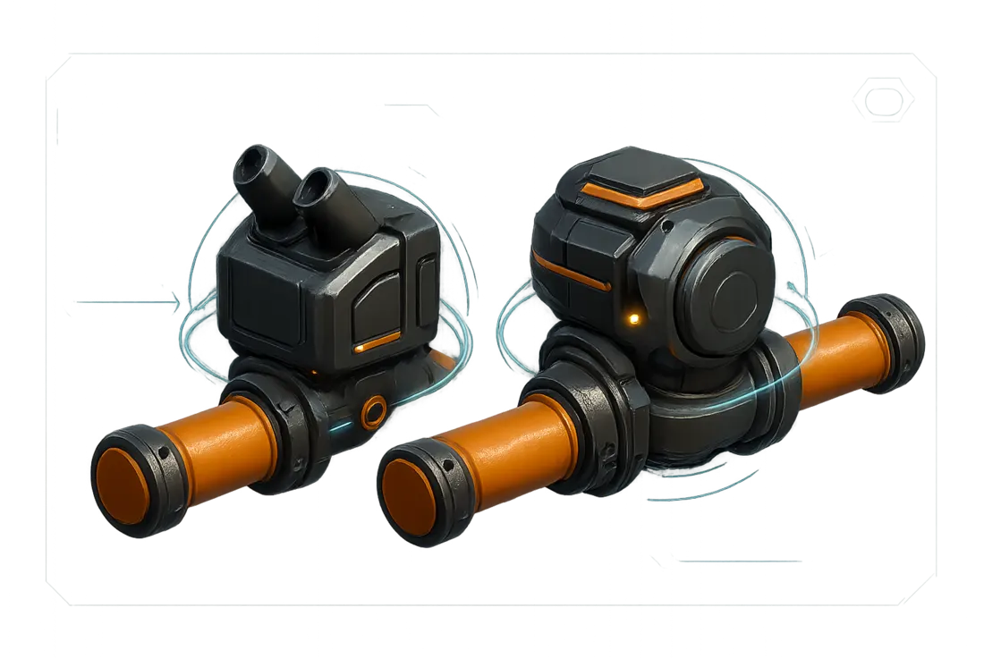
- They prevent backflow — pumps are one-directional.
- They generate a blue hologram ring that stops where their head lift ends. The ring can travel at most
100 m, so on a long diagonal pipeline you may not see it stop. - They have no flow rate limit of their own; Mk.1 and Mk.2 pipes both work with them.
- They snap to the hologram ring of other pumps, which makes spacing a long climb easy.
- Pump head lift does not stack with another pump’s — but it does stack with head lift gained from gravity after the pump.
Pumps in four situations
InteractiveOne pump lifts everything behind it: all three branches can rise 20 m together. The hologram ring shows where the head lift ends and travels at most 100 m.
The four cases lesson 4 draws.
- Head lift is measured from the centre of the pipe or pump, and always upwards — never downwards. Fluids flow down on their own; they do not need to be pushed.
- The output side always has the striped ring. If you are not sure which way a pump faces, look for the stripes.
- A pump on a flat, horizontal pipe shows about
1.5 mof head lift. That is the default pressure, not a bug. - Pumps also apply head lift when they sit on the horizontal part of a pipeline — the fluid will rise once the pipe starts going up.
Knowledge check
OptionalA pipeline has two bumps: the first is 18 m tall, the second 22 m. The pump sits 9 m up on the first pipe. Is that enough for both?
Fluid buffers
Buffers store fluid — and, less obviously, they generate head lift that depends on how full they are.
| Buffer | Capacity | Height | Port height |
|---|---|---|---|
| Fluid Buffer | 400 m³ | 8 m | 1.5 m |
| Industrial Fluid Buffer | 2400 m³ | 12 m | 1.5 m |
To fill a buffer, the connected pipe has to supply a head lift equal to the buffer’s height: 8 m for the small one, 12 m for the industrial one. A machine’s 10 m will fill a small buffer, but not an industrial one.
What a buffer gives back is proportional to the fluid inside it. A half-full industrial buffer generates 6 m of head lift, a half-full small buffer 4 m.
Fluid buffer
InteractiveIt needs about 300 m³ inside before it reaches 1.5 m of head lift and can output as fast as fluid flows in.
Head lift follows the fill height; the 1.5 m port line is the manual's output threshold.
Buffers that are connected to each other try to balance themselves out. In series that leads to heavy sloshing back and forth; in parallel the odd sloshing is mostly resolved.
Buffers balancing each other
InteractiveBuffers connected to each other try to balance themselves out.
Valves
Valves do two things: they stop backflow, and they cap the flow rate of a pipe.
- A – the Valve – is a pipe attachment that does not allow backflow and makes it possible to limit the pipe’s flow rate.
- Set the limit by moving the slider or typing a number — press Enter to confirm.
- Valves have a slight display bug: the flow rate they show is inaccurate. Used correctly they still do their job.
The catch is the same one as everywhere else in this guide. When the pressure inside the pipe is not big enough — that is, when the pipe is not full — a valve outputs less than the limit it is set to. The manual’s example: 240 m³/min arriving, valve set to 120, and only 60 m³/min coming out. Once the pipe is full and the pressure is back, the valve passes its 120.
Valve lab
InteractiveThe limits add up to the input flow. Every branch gets exactly what it was set to.
A valve only reaches its limit once its input pipe is full; a branch without a valve is not predictable.
Valves in series
InteractiveThree valves set to 120 m³/min, fed with 300 m³/min.
Knowledge check
OptionalA pipeline feeds a machine, with a on the input side to prevent backflow. The machine fills up, and so does the input pipe. What happens at the valve?
Troubleshooting
Pipe problems fall into three families. Work through them in order — the later ones are much harder to diagnose.
Troubleshooter
InteractiveWhat are you seeing?
A missing or bad connection — the cheapest of the three to fix, and worth ruling out first.
Usually caused by overestimating the 10 m a machine provides, or by a badly placed pump.
The complex one. Only try to solve this once you are sure it is not a connection or a head lift problem.
The three families of pipe problem from lesson 7, in the order the manual recommends.
Manifolds
A manifold is any arrangement of pipes and junctions connected in series. Because pipes and junctions are bidirectional, a manifold ultimately balances itself.
That self-balancing is what makes manifolds attractive: build a row of machines, run one feed pipe past them, and the network sorts out the distribution on its own. As easy as that sounds, there are rules that decide whether it works well or badly.
- 1 Build the feed pipeline level with or above the machine inputs
Never below them. Head lift is the same for every pipe in the network, so a feed pipe that sits low has to raise the whole network to the same fluid height before any machine is served.
- 2 Prefill the machines
A machine input can hold
50 m³of fluid. Make sure it is full — a full internal storage means the machine only ever consumes as much as it actually needs. - 3 If problems remain, close the network into a loop
A loop injects fluid from both ends and avoids losses. It also resolves the backflow issue from knowledge check 3.
Feed pipe height
InteractiveManifold rule 1: build the feed pipeline level with or above the machine inputs.
Closing the network into a loop
InteractiveManifold rule 3, and the fix for the backflow of knowledge check 3.
Recycling byproducts
Some processes — aluminium above all — hand you a fluid byproduct that has to go somewhere. Feeding it straight back is the obvious move, and it is a trap.
Basic aluminium processing: 120/min Bauxite and 180 m³/min Water go into the first Refinery, which produces 120 m³/min Alumina Solution plus 50/min Silica. The second one turns that Alumina Solution and 60/min Coal into 180/min Aluminum Scrap — and 60 m³/min of Water.
Most pioneers try to feed that water back into the first refinery. Without any additional work the second refinery gets clogged: the junction in front of the first refinery now carries 240 m³/min — 180 fresh plus 60 returned — into an input that only takes 180.
Aluminium water loop
InteractiveThe junction in front of the first refinery now carries 240 m³/min into an input that only takes 180 m³/min. The second refinery clogs, and a clogged output stops production entirely.
The four solutions of lesson 9, with the manual's own judgement of each.
Flow rate filters
Two small builds that smooth out a jumpy flow rate so you can actually read it.
These are not really “circuits” — they are pipe builds — but it is easier to refer to them that way. Both leave the valve limit untouched: they change how steady the flow is, not how much of it there is. If a circuit feels unstable, try adding pumps to its input and output.
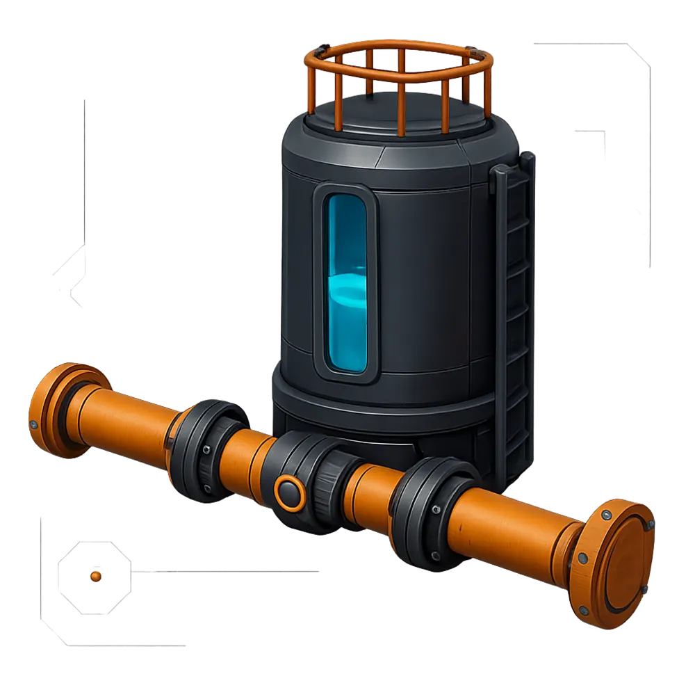
The Flow Equalizer reduces flow rate fluctuations. It stores fluid when there is too much and discharges it when there is too little. In the manual’s example a pipe swinging between 30 and 150 m³/min comes out at 65 to 115 m³/min.
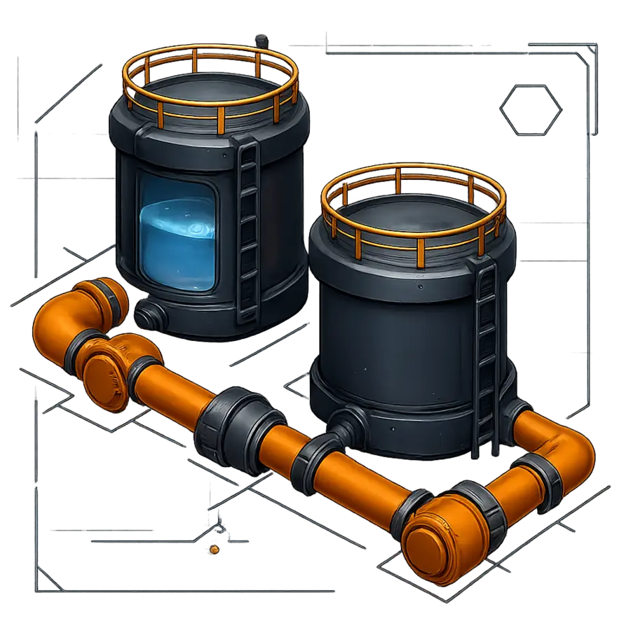
The Flow Compensator is an improved Equalizer — you could call it the Equalizer Mk.2. It reduces fluctuations even more, but it is much slower and a bit unstable. The same 30 to 150 m³/min pipe leaves it at roughly 90 m³/min. Even the very dynamic Mk.2 pipes, which often fluctuate wildly, can be tamed by it.
Flow rate filters
InteractiveThe ranges lesson 10 reports for the same fluctuating pipe.
Variable priority junctions
Two builds that turn a plain junction into a priority device: one for inputs, one for outputs.
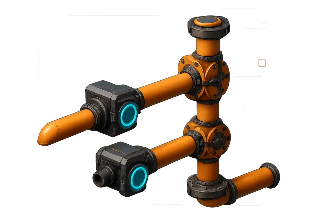
The prioritises the lowest input. The pipe at the very bottom flows freely, while the ones above it are blocked — unless the output allows more flow. Remember to power the pumps. For more priority levels, extend the VIP upwards with more inputs; the minimum is 2 inputs and 1 output.
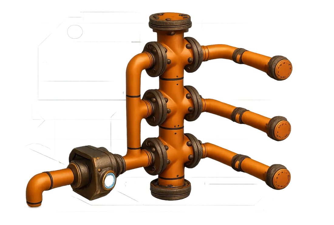
The prioritises the lowest output. It fills the output pipe at the very bottom first; once that is full, it fills the next one up. It is essentially an expanded . Valve limits on the branches set the desired flow per pipe. Extend it upwards for more levels; the minimum is 1 input and 2 outputs.
VIP / VOP simulator
InteractiveThe lowest input flows freely; the ones above it only get what is left. Total through the junction: 180 m³/min.
A visual model of lesson 11: priority is resolved from the bottom pipe upwards.
Head lift tricks
Three builds that use head lift as a mechanism rather than as a constraint.
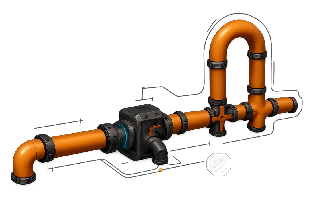
The diverts any flow that does not fit into the bottom pipe. It only becomes active once the bottom exit backs up — then the extra flow moves over a little “heap”, around 8 m tall. The pump is there to give the fluid enough head lift to cross that rise no matter what; it does not make the overflow active any earlier.
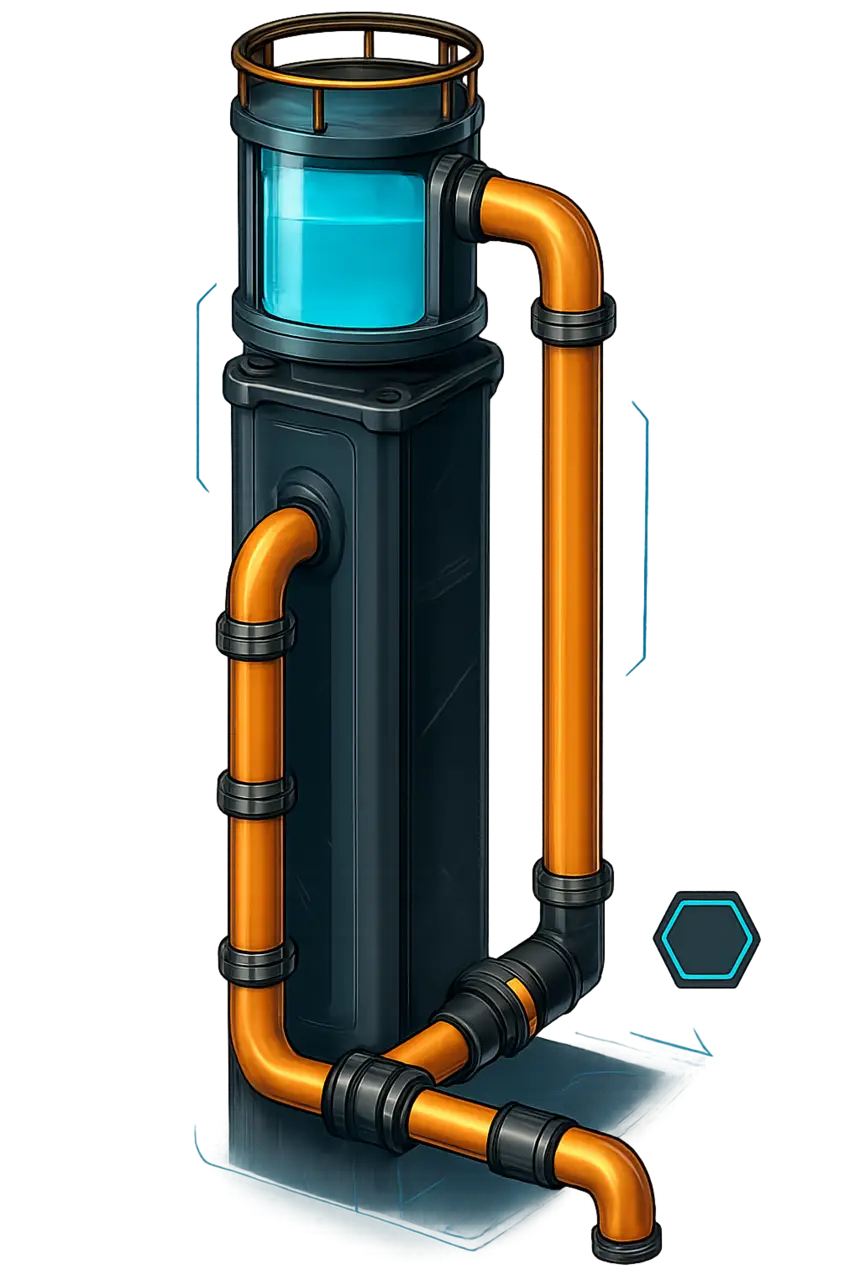
The Water Tower is a Fluid Buffer many metres off the ground. Every pipe connected below it runs without pumps, as long as it stays below the buffer. The valve set to 0 m³/min in the diagram is what keeps the tower full: without it, the tower has to be constantly refilled.
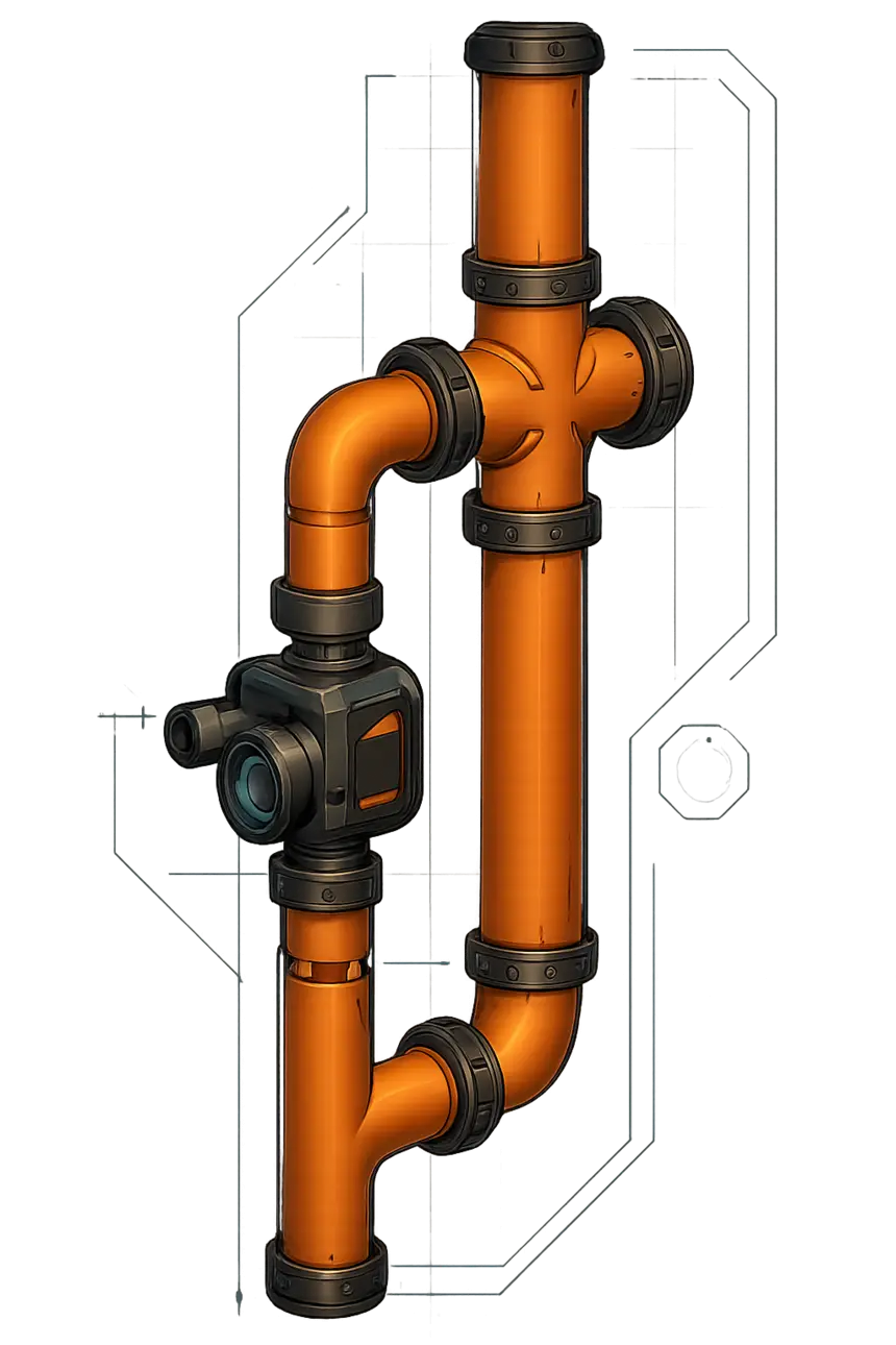
The Two-Way Pump lets fluid move both up and down. It gives the pipe connected to it the head lift to rise, but does not prevent backflow. That makes it a good partner for the Water Tower — and it means fluid can run backwards during a blackout, which is sometimes exactly what you want and sometimes not.
Sample solutions
Four applied examples that put the circuits of this chapter to work.
Applied examples
InteractiveSolving water backup in aluminium processing with a VIP junction
The second Refinery hands back 60 m³/min of water while the first one turns 120 m³/min of Alumina Solution into Aluminum Scrap. A junction gives the returned water priority, so the fresh water line is throttled to whatever is left — <180 m³/min — and nothing backs up.
The four examples on the manual's last page.
Glossary
The vocabulary this guide uses, in one place.
- Flow Rate
- How much fluid is moving through a pipe right now, in m³/min. It fluctuates; the true value is the average over time.
- Max Flow Rate
- The ceiling of a pipe or a machine output: 300 m³/min on Mk.1 pipe, 600 m³/min on Mk.2. A machine empties itself at this speed whenever it can.
- Current Amount
- The internal volume of a pipe — the bubble icon in its UI. How full it is decides how fast it can flow and whether it transmits head lift.
- Head Lift
- The maximum height fluid can be pushed to, in metres. Transmitted through full pipes without declining; measured from the centre of a pipe or pump, upwards only.
- Work Pressure
- The second kind of pressure in a pipe. It divides evenly over the outputs of a network, which is why 800 m³/min over three pipes gives 266.66 each. Not directly manipulable.
- FluidBox
- The internal fluid container of a pipe, machine or buffer. Everything in this guide is really a statement about how full some FluidBox is.
- Pipeline Junction
- The four-way pipe connector. It has no flow rate limit of its own — only the pipe segments around it are capped.
- Pipeline Pump Mk.1 / Pipeline Pump Mk.2
- A pipe attachment that raises head lift (Mk.1: 20 m, Mk.2: 50 m), prevents backflow and has no flow rate limit. It never increases flow rate.
- Valve
- A pipe attachment that blocks backflow and caps the flow rate to a set limit. It only reaches that limit once its input pipe is full.
- Fluid Buffer
- A storage tank: 400 m³ and 8 m tall, or 2400 m³ and 12 m tall. It generates head lift in proportion to its fill level.
- Manifold
- Pipes and junctions connected in series, feeding a row of machines. Because pipes are bidirectional, a manifold balances itself out.
- VIP — Variable Input Priority Junction
- A build that prioritises the lowest of several inputs; the upper ones only flow when the output has capacity left.
- VOP — Variable Output Priority Junction
- A build that fills the lowest of several outputs first and only moves to the next one up once that has backed up.
- Overflow Junction
- A junction with one exit behind a small rise, so that only the flow which does not fit into the main exit is diverted over it.
- Flush
- The function that empties a pipe segment. Useful as a measuring tool: flush, then watch how the segment refills.
Source and credits
Where this guide comes from, and what we changed.
- @McGalleon#8273 (Discord)
- u/MkGalleon (Reddit)
- Manual version
- 1.4
- Date
- 21.08.2022
- Written for
- Update 5 + Update 6 (+ onward)
“These are only the most useful special circuits. There are a few more, but they are not practical for the general factory purposes of FICSIT pioneers.”
“Hopefully, this manual could help you solve some of your factory issues or answer some of your questions.”
SatisfactoryBase is not the author of this manual. We rewrote its text so it reads as a guide rather than a slide deck, rebuilt every diagram as a responsive SVG, and turned its worked examples into calculators and knowledge checks. The technical content — every rule, value and conclusion — is the manual’s.
The manual predates the current release. We kept it faithful to its source rather than re-testing every statement against the latest patch, so treat the numbers as the manual’s findings, not as independently verified data.